Week 9 [Mon, Oct 12th] - Topics
The analysis process for identifying objects and object classes is recognized as one of the most difficult areas of object-oriented development. --Ian Sommerville, in the book Software Engineering
Sidebar: Domain Modeling
Domain modeling is modeling the i.e., to model how things actually work in the real world. Domain modeling is useful in understanding the problem domain, which is essential to the success of a project.
Domain modeling can be done using:
- a domain-specific modeling notation if such a notation exists (e.g., a modeling notation specific to the banking domain might have elements to represent loans, accounts, transactions, etc.),
- or a general-purpose modeling notation, such as UML (e.g., you can use an activity diagram to model the workflow of processing a loan application),
- or even other general-purpose notations (e.g., you can use an organization chart to model the employee hierarchy of a company).
When building an OOP system, it makes sense to build OOP models of the problem domain, given OOP aspires to emulate the objects in the real world.
The UML models that capture class structures in the problem domain are called conceptual class diagrams. They are in fact a lighter version of class diagrams, and sometimes also called OO domain models (OODMs). The latter name is somewhat misleading as conceptual class diagrams (CCDs) are actually only one type of domain model that can model an OOP problem domain.
Example The CCD of a snakes and ladders game is given below.
Description: The snakes and ladders game is played by two or more players using a board and a die. The board has 100 squares marked 1 to 100. Each player owns one piece. Players take turns to throw the die and advance their piece by the number of squares they earned from the die throw. The board has a number of snakes. If a player’s piece lands on a square with a snake head, the piece is automatically moved to the square containing the snake’s tail. Similarly, a piece can automatically move from a ladder foot to the ladder top. The player whose piece is the first to reach the 100th square wins.
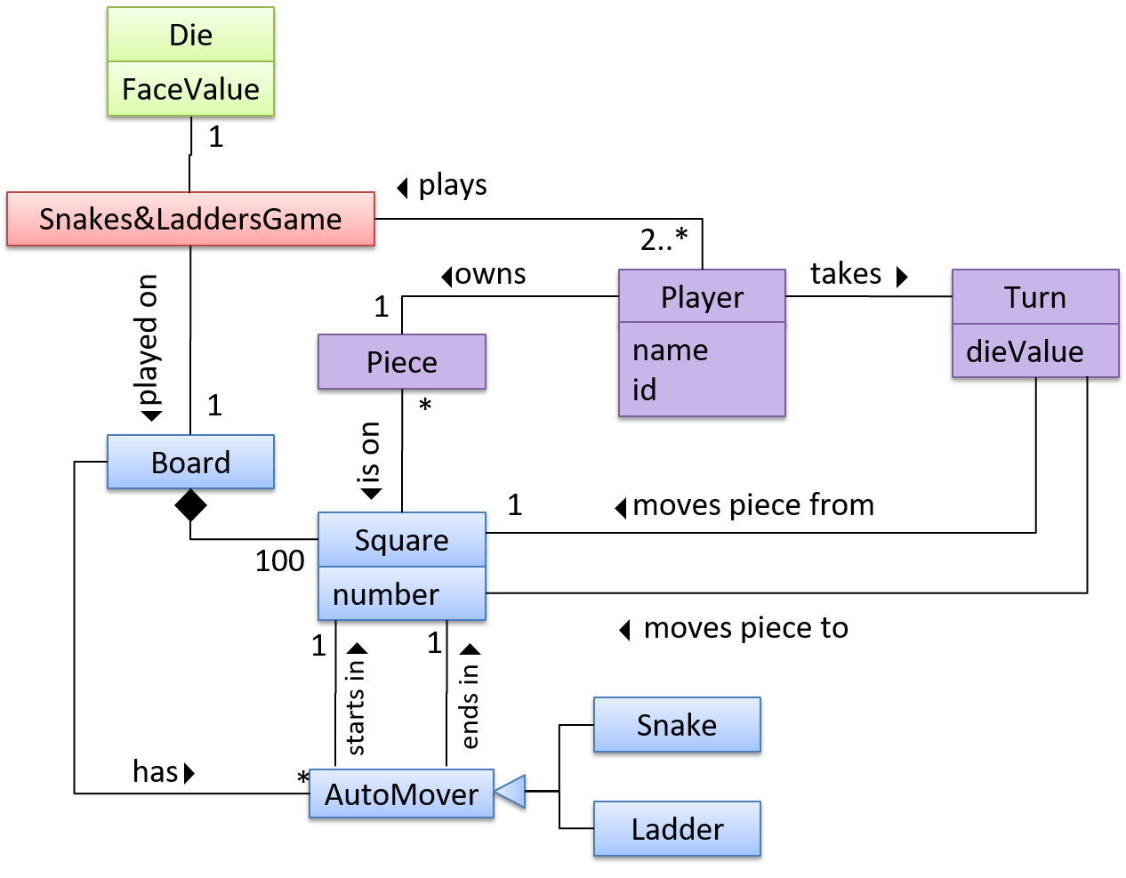
CCDs do not contain solution-specific classes (i.e., classes that are used in the solution domain but do not exist in the problem domain). For example, a class called DatabaseConnection could appear in a class diagram but not usually in a CCD because DatabaseConnection is something related to a software solution but not an entity in the problem domain.
CCDs represent the class structure of the problem domain and not their behavior, just like class diagrams. To show behavior, use other diagrams such as sequence diagrams.
CCD notation is a subset of the class diagram notation (omits methods and navigability).
Guidance for the item(s) below:
Activity diagrams is the last UML diagram type you'll be learning in this course, and probably the easiest and most intuitive of the lot. You've heard about 'flow charts', right? Well, this is the UML equivalent of that.
Follow up notes for the item(s) above:
Here are some examples showing the steps of drawing an activity diagram to match a given workflow.
Guidance for the item(s) below:
A few weeks ago, you learned how to interpret UML diagrams. More recently, you learned how to draw diagrams to match code. There's a third use of models: as an aid for coming up with a design before the code is written.
While this course doesn't ask you to come up with detailed designs before writing code (i.e., our approach leans closer to the agile design rather than the full design upfront approach), this third use of models come in handy at times. Let's learn a bit about that too.
You can use models to analyze and design software before you start coding.
Suppose you are planning to implement a simple minesweeper game that has a text-based UI and a GUI. Given below is a possible OOP design for the game.

Before jumping into coding, you may want to find out things such as,
- Can this class structure produce the behavior you want?
- What API should each class have?
- Do you need more classes?
To answer these questions, you can analyze how the objects of these classes will interact with each other to produce the behavior you want.
As mentioned in [Design → Modeling → Modeling a Solution → Introduction], this is the Minesweeper design you have come up with so far. Our objective is to analyze, evaluate, and refine that design.
Let us start by modeling a sample interaction between the person playing the game and the TextUi object.
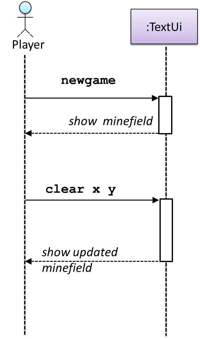
newgame and clear x y represent commands typed by the Player on the TextUi.
How does the TextUi object carry out the requests it has received from the player? It would need to interact with other objects of the system. Because the Logic class is the one that controls the game logic, the TextUi needs to collaborate with Logic to fulfill the newgame request. Let us extend the model to capture that interaction.
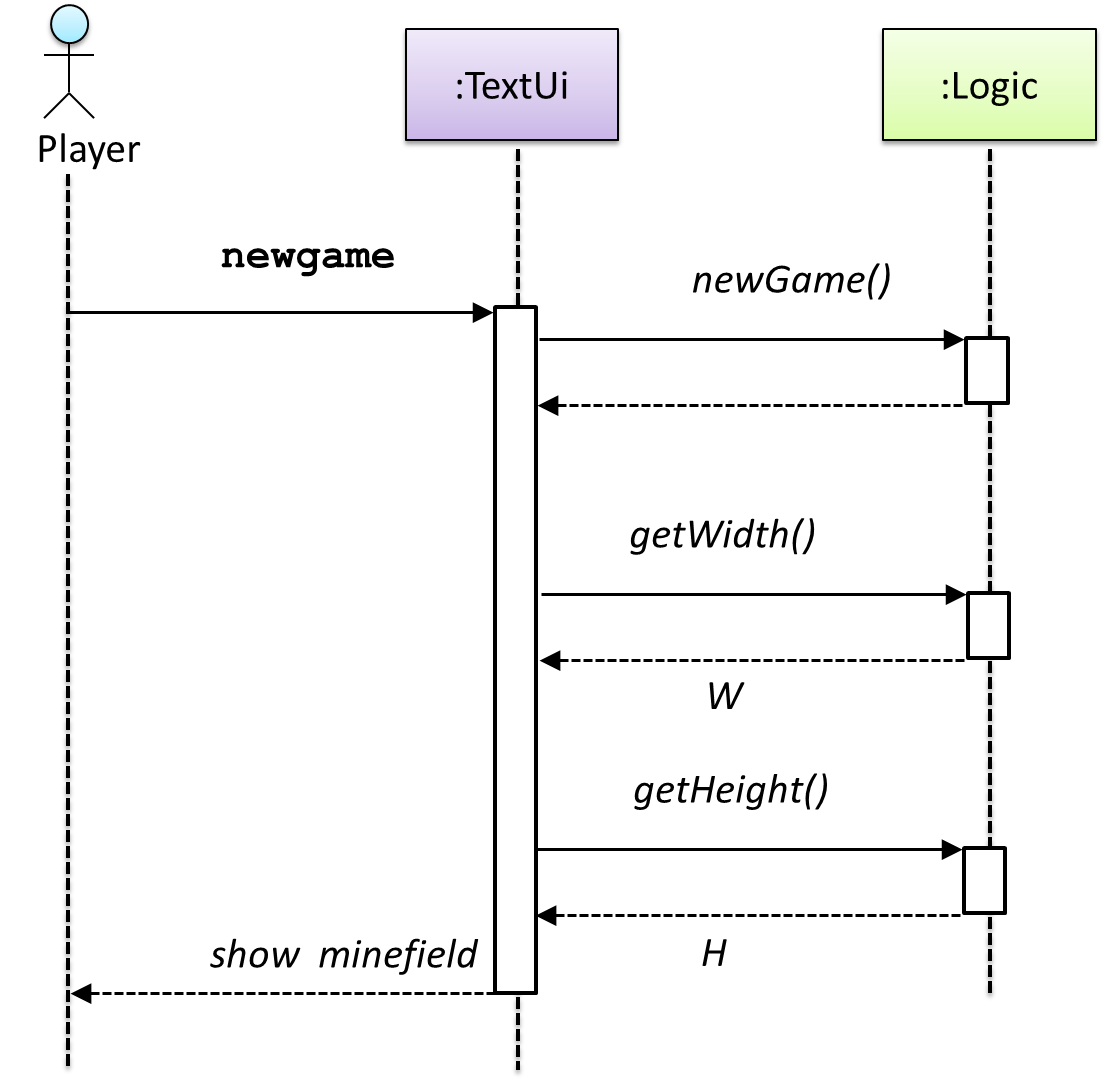
W = Width of the minefield; H = Height of the minefield
The above diagram assumes that W and H are the only information TextUi requires to display the minefield to the Player. Note that there could be other ways of doing this.
The Logic methods you conceptualized in our modeling so far are:
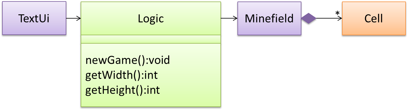
Now, let us look at what other objects and interactions are needed to support the newGame() operation. It is likely that a new Minefield object is created when the newGame() method is called.
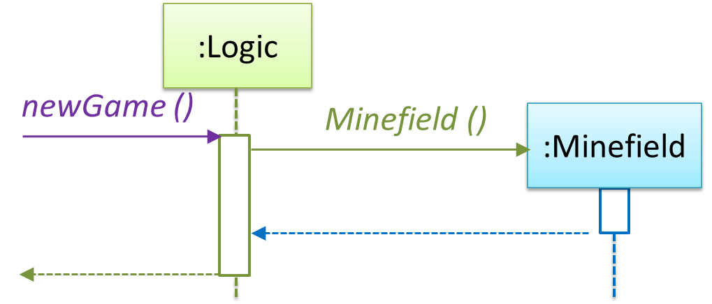
Note that the behavior of the Minefield constructor has been abstracted away. It can be designed at a later stage.
Given below are the interactions between the player and the TextUi for the whole game.

Note that can be used when discovering/defining the architecture-level APIs.
Guidance for the item(s) below:
You've already encountered architecture diagrams in your tP. Pretty soon, you might have to update that diagram to match your new product. Given below are just a brief note about drawing architecture diagrams.
While architecture diagrams have no standard notation, follow these guidelines when drawing them.
- Name each component by its responsibility, not its current implementation.
ExampleStoragestays accurate even if the implementation changes;JsonFileHandlerbecomes inaccurate if you switch to a database later. - Show only what is architecturally relevant. If the architecture has more than a handful of components, it is a sign that it has slipped to a lower level of abstraction than it should be.
- Use familiar symbols, and explain them in a legend. e.g., a drum shape is widely understood to represent a database. Explain any symbol whose meaning may not be obvious. If you need two kinds of arrow, make them visually different and label both in the legend.
- Avoid the indiscriminate use of double-headed arrows if arrow directions can be used more meaningfully.
Example Consider the two architecture diagrams of the same software given below. Because Diagram 2 uses double-headed arrows everywhere, the important fact that GUI has a genuinely bidirectional dependency with the Logic component is no longer visible.

Guidance for the item(s) below:
These principles build on top of the design fundamentals you learned earlier (i.e., abstraction, coupling, cohesion).
Liskov substitution principle (LSP): Derived classes must be substitutable for their base classes. -- proposed by Barbara Liskov
LSP sounds the same as substitutability but it goes beyond substitutability; LSP implies that a subclass should not be more restrictive than the behavior specified by the superclass. As you know, However, if LSP is not followed, substituting a subclass object for a superclass object can break the functionality of the code.
Example Suppose the Payroll class depends on the adjustMySalary(int percent) method of the Staff class. Furthermore, the Staff class states that the adjustMySalary method will work for all positive percent values. Both the Admin and Academic classes override the adjustMySalary method.
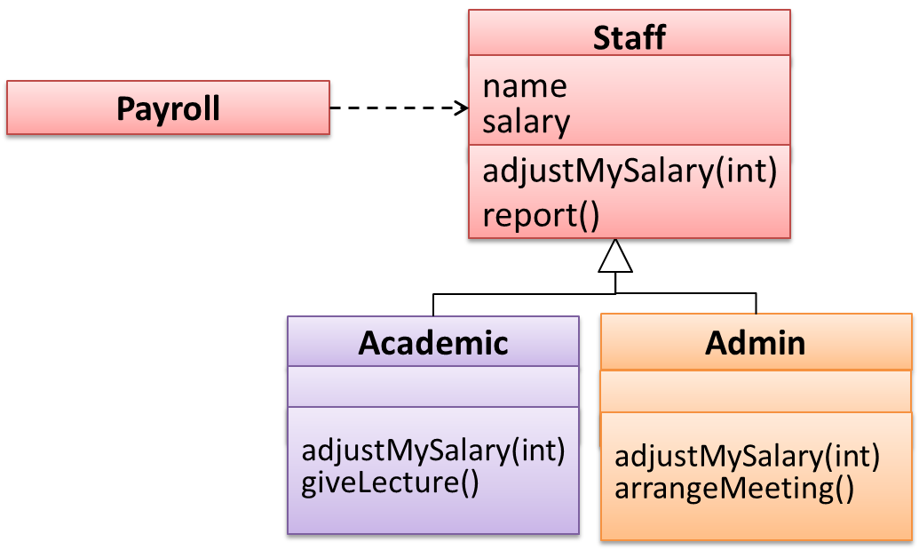
Now consider the following:
- The
Admin#adjustMySalarymethod works for both negative and positive percent values. - The
Academic#adjustMySalarymethod works for percent values1..100only.
In the above scenario,
- The
Adminclass follows LSP because it fulfillsPayroll’s expectation ofStaffobjects (i.e., it works for all positive values). SubstitutingAdminobjects forStaffobjects will not break thePayrollclass functionality. - The
Academicclass violates LSP because it will not work for percent values over100as expected by thePayrollclass. SubstitutingAcademicobjects forStaffobjects can potentially break thePayrollclass functionality.
The Open-Closed Principle aims to make a code entity easy to adapt and reuse without needing to modify the code entity itself.
Open-closed principle (OCP): A module should be open for extension but closed for modification. That is, modules should be written so that they can be extended, without requiring them to be modified. -- proposed by Bertrand Meyer
In object-oriented programming, OCP can be achieved in various ways. This often requires separating the specification (i.e., interface) of a module from its implementation.
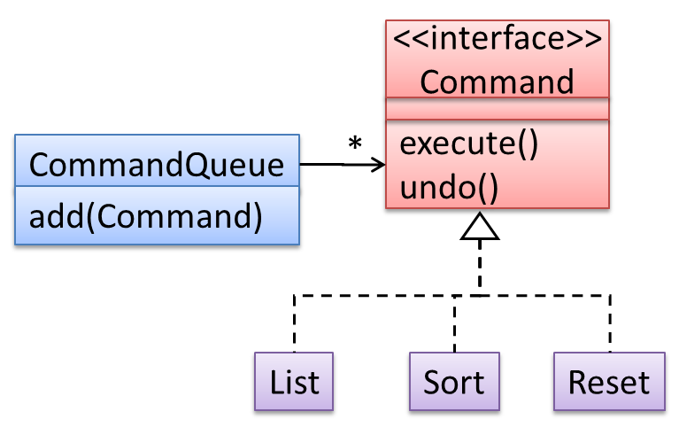
Example In the design given below, the behavior of the CommandQueue class can be altered by adding more concrete Command subclasses. For example, by including a Delete class alongside List, Sort, and Reset, the CommandQueue can now perform delete commands without modifying its code at all. That is, its behavior was extended without having to modify its code. Hence, it is open to extensions, but closed to modification.
Example The behavior of a Java generic class can be altered by passing it a different class as a parameter. In the code below, the ArrayList class behaves as a container of Students in one instance and as a container of Admin objects in the other instance, without having to change its code. That is, the behavior of the ArrayList class is extended without modifying its code.
ArrayList students = new ArrayList<Student>();
ArrayList admins = new ArrayList<Admin>();
Guidance for the item(s) below:
If you liked the principles covered above, given below are a few more widely used principles most of which are optional in this course (they were moved to the optional topics in order to reduce the course workload).
The only examinable thing is the term SOLID principles.
Guidance for the item(s) below:
Remember these three topics that we covered early in the course?
The sequential model, also called the waterfall model, views software development as a linear process, with the project progressing through the development stages in order. The name waterfall stems from how the model is drawn to look like a waterfall (see below).
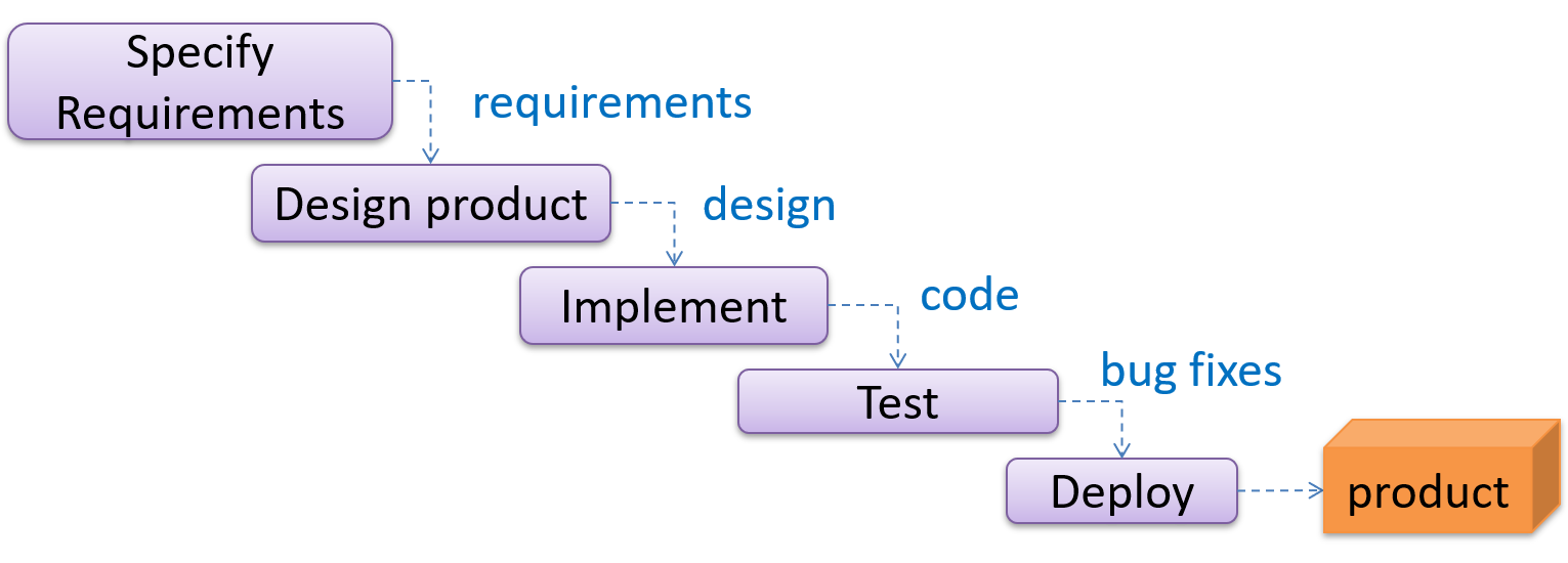
When one stage of the process is completed, it produces some to be used in the next stage. For example, the requirements stage produces a comprehensive list of requirements to be used in the design stage.
A strict sequential model project moves only in the forward direction i.e., each stage is completed before starting the next. For example, once the requirements stage is over, there is no provision for revising the requirements later. In practice the model is often relaxed to let a stage send work back to the one before it, although doing so means redoing work that was already treated as finished.
This model can work well for a project that solves a well-understood problem, in which case the requirements can remain stable and the effort can be estimated accurately. Furthermore, as each stage has a well-defined outcome, progress is easy to track: it is visible from which stage the project is in. Progress within a long stage, which is where an overrun usually builds up, stays much harder to see.
However, real-world projects often tackle problems that are not well-understood at the beginning, which makes those projects unsuitable for this model. For example, target users of a software product may not be able to state their requirements accurately at the start of the project if they have not used a similar product before.
A second weakness is that feedback arrives late. Each stage's output is checked mainly by the stage that follows it, so integration and contact with real users come near the end. A mistake made while gathering requirements or designing therefore tends to surface at the point where going back to completed work costs the most.
The iterative model advocates producing the software by going through several iterations. Each iteration could go through all the stages of the SDLC, from requirements gathering to deployment.
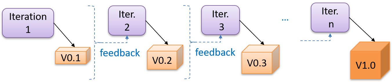
Each iteration produces a new version of the product, building upon the previous version. Feedback from each iteration is factored into the subsequent iterations. For example, if an implementation task took longer than expected, the effort estimate for similar tasks in future iterations can be adjusted. Similarly, if a feature introduced in the current iteration was not well-received by target users, it can be removed or tweaked in the next iteration.
The two models divide a project along different lines.
- A sequential project is divided by activity: a stage is 'requirements' or 'testing', and it ends when that activity is finished for the whole product.
- An iterative project is divided into bounded cycles instead: an iteration runs through several activities and ends in a result the team can learn from.
The iterative model can use a breadth-first or depth-first approach.
- In the breadth-first approach, an iteration evolves all major components and all functionality areas in parallel, producing a working product at the end of each iteration i.e., most features and most are updated in every iteration.
- In the depth-first approach, an iteration focuses on fleshing out only some components or some functionality area. Accordingly, early depth-first iterations might not produce a working product.
Iterating and incrementing are two different things, and most projects do both. To iterate is to rework something that already exists, in the light of feedback; to increment is to add to it. That is why the two are usually named together, as an iterative and incremental approach.
What an iteration delivers is called an increment: a usable improvement or addition to the product, not merely a new version of the code.
Ideally, an iteration should produce not only progress but also new knowledge. Before starting one, decide what would show it succeeded -- a condition the result must satisfy, a test that must pass, or a demonstration to a target user -- and what decision the answer will drive.
Example An iteration can add a new feature while helping the team estimate the effort for similar future features or assess the advantages and disadvantages of the approach used to implement it.
Example Taking a Minesweeper game as an example:
- breadth-first iterations will deliver a fully playable version early. These early versions may have primitive functionality, e.g. a rudimentary text-based UI, fixed board size, limited minefield layouts. This functionality (and the corresponding components) will then be improved in later iterations.
- an early depth-first iteration could deliver the full user interface (UI) but with no game logic at all. Alternatively, an early iteration could focus on just the logic for generating initial layouts of the minefield. Neither is a playable version of the game, but both can collect early feedback -- on the UI in the first case, on the minefield layouts in the second. That feedback then guides later iterations.
A project can be done as a mixture of breadth-first and depth-first iterations i.e., an iteration can contain some breadth-first work as well as some depth-first work, or some iterations can be breadth-first while others are depth-first.
Whichever shape the iterations take, an early one is a chance to find out you were wrong while changing course is still cheap. That makes the assumptions whose failure would cost the most -- an unproven technology, an unfamiliar user need, a performance target nobody has hit yet -- worth putting into an early iteration rather than a late one.
Guidance for the item(s) below:
Let's continue that thread to learn about some SDLC process models that are commonly used in the industry.
Scrum is a lightweight agile framework rather than a complete process. It fixes a small set of roles, events, and artifacts, and leaves the team to fill in the rest with practices of its own choosing. The description below follows the Scrum Guide.
A Scrum team has three accountabilities:
- The Product Owner, who represents the stakeholders and decides what the product needs next
- The Scrum Master, who is accountable for the team using Scrum well
- The Developers, a cross-functional group who do the analysis, design, implementation, and testing
A Scrum project is divided into short iterations called Sprints. Sprints are time-boxed (i.e., restricted to a fixed duration) at one month or less, and every Sprint in a project has the same length. One to four weeks is the common choice.
A Sprint contains all the work done in it, together with all its events. It opens with Sprint Planning, where the team selects the work and agrees on a Sprint Goal, and the Developers coordinate daily as the work proceeds. It ends with two distinct meetings: a Sprint Review, where the team and stakeholders inspect the Increment and decide what the product needs next, and a Sprint Retrospective, where the team inspects how it worked and chooses improvements. The next Sprint begins immediately after.
During each Sprint, the team creates a potentially deliverable Increment (for example, working and tested software). The work comes from the Product Backlog, a prioritized set of high-level requirements for the product as a whole. The items selected for the current Sprint form the Sprint Backlog.
Within a Sprint the Sprint Goal stays fixed, but the plan for reaching it does not. The team updates the Sprint Backlog as it learns more, and can renegotiate the scope with the Product Owner as long as the Sprint Goal survives. The Sprint must end on time; work that is not completed returns to the Product Backlog.
Scrum enables self-organizing teams, which rely on frequent and direct communication among all team members and disciplines rather than on documents handed from one to the next.
Scrum assumes that customers will change their minds about what they want (often called requirements churn) and that unforeseen problems cannot be planned for in advance. It therefore takes an empirical approach: instead of trying to define the problem fully up front, it maximizes the team's ability to deliver quickly and respond to requirements as they emerge.
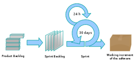
The Daily Scrum is a short daily meeting in which the Developers synchronize their plans, surface whatever is blocking them, and decide what needs to be taken up separately. It is not a problem-solving meeting.
Example A common way to run it is for each member to say what they did since the previous Daily Scrum, what they plan to do next, and what is in their way.
The following description was adapted from the XP home page, emphasis added:
Extreme Programming (XP) stresses customer satisfaction. Instead of delivering everything you could possibly want on some date far in the future, this process delivers the software you need as you need it.
XP aims to empower developers to confidently respond to changing customer requirements, even late in the lifecycle.
XP emphasizes teamwork. Managers, customers, and developers are all equal partners in a collaborative team. The team self-organizes around the problem to solve it as efficiently as possible.
XP aims to improve a software project in five essential ways: communication, simplicity, feedback, respect, and courage. Extreme Programmers constantly communicate with their customers and fellow programmers. They keep their design simple and clean. They get feedback by testing their software starting on day one. With this foundation, Extreme Programmers are able to courageously respond to changing requirements and technology.
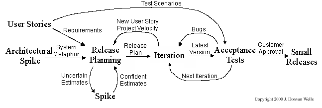
What makes XP 'extreme' is not the practices it uses but how often it uses them. Each one was already considered good; XP pushes each to the point where it happens continuously rather than in a scheduled phase:
- releases are small and frequent, rather than saved up for a milestone;
- code is integrated continuously, rather than merged near the end (continuous integration);
- tests are written before the code they test, rather than after (test-driven development);
- the design is refactored constantly, rather than in a cleanup phase;
- two programmers write the code together at one keyboard, so it is reviewed as it is written rather than in a scheduled review (pair programming).
Follow up notes for the item(s) above:
AI's impact on » SDLC process models
AI changes the cost of the work, not the need for a plan.
- Picking the right process model matters less now. Building a version of the software used to take weeks, so it was worth arguing about how to order the stages. When an agent can produce a version in hours, less rides on that choice, and code-and-fix starts to look tempting again.
- Knowing what you want, and checking what you got, matter more. Those are the two things an agent cannot do for you. So the useful part of a process model is now its outputs, not its stages: a clear requirement, an agreed design, and a test that says what 'done' means. These are also what you hand to an agent. Give it a vague one, and you will get the wrong thing built quickly and confidently.
- Short iterations matter more, not less. When a wrong turn takes minutes, you want frequent points where a human looks at real output.
Guidance for the item(s) below:
As you will be updating documentation of your project soon, here are some guidelines to help you with that.